Table Of Contents
- Introduction to Storage Types
- Storage Performance Metrics and their Interdependencies
- A short excursion into queuing theory
- Performance Scalability
- Predictability of Performance
- Node-Level Performance Measurement
- Measuring Horizontal Performance Scalability
- System Architecture
- Performance Profiling and Tuning
- When Building for NVMe, Performance Can't Be an Afterthought
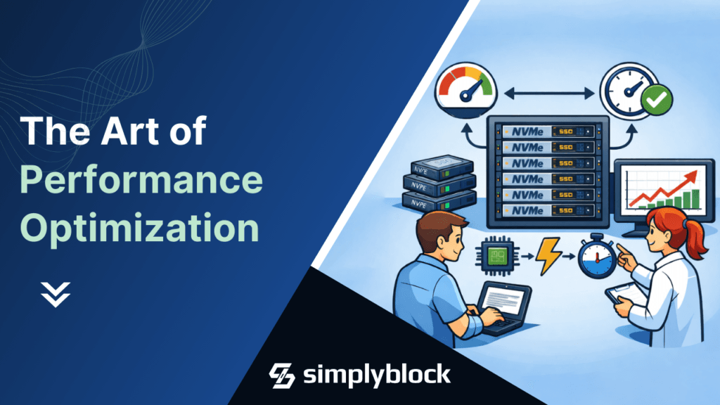
Building a high-performance and low-latency distributed storage system isn’t easy. At simplyblock, we’ve spent the last few years building and optimizing to squeeze every last drop of performance from modern NVMe storage devices and network infrastructure. And, we learned more than just a thing or two about performance measurement and optimization.
While the journey isn’t finished yet, the system has proven itself in production at a multi-petabyte scale, and will soon be deployed in some of the world’s largest private clouds.
I think now’s a good time to pause, recap our efforts in building simplyblock, and share our lessons learned with a technical deep-dive.
The first sections are mostly theoretical background. If you feel comfortable with the topic, you can jump straight to the meaty bits. Otherwise, let me get you up to speed with the basics first.
Introduction to Storage Types

Storage is typically segmented into block-, file-, and object-storage. Block storage sits below file and object storage and provides the foundation for other storage engines, such as key-value stores and database storage backends, which are implemented on top of it.
Simplyblock implements high-performance distributed block storage and an additional (yet unreleased) layer of shared file storage.
Storage Performance Metrics and their Interdependencies
Data storage performance is measured by two main indicators, which can further be split into separate sub-indicators for read/write or reported as a single indicator defined as a read/write mix (e.g., 75%/25%):
- Throughput can be broken down into sequential throughput, measured in GB/s, and random-access throughput, measured in IOPS across block sizes (most commonly 4K).
- Latency is measured as the round-trip time for a single I/O request to complete.
Between the two indicators, there is a bidirectional relationship. As system load increases toward its maximum throughput (IOPS or GB/s), latency also increases proportionally (though not linearly).

As you can see in the figure above, during the first phase of load increase, a higher amount of IOPS goes hand in hand with a moderate increase in latency. Once IOPS are saturated, additional load will increase queue length (and thus latency), but won’t increase throughput any further.
Therefore, a single latency number (in ms or μs) is meaningless without its queue depth. Always ask what concurrency the measurement used.
This is no different from the dynamics in a traffic jam. It’s similar to the lunchtime queue at a cafeteria or the wait list for a doctor’s appointment. If all concurrent “processing units” (lanes, cashiers, or doctors) are busy, requests queue up, and the wait time (“latency”) increases.
Conversely, the minimum latency also influences the maximum achievable throughput, albeit indirectly. Here is the fundamental relationship (specifically worded for data storage):
Concurrency (QD) = IOPS × Latency → IOPS = Concurrency (QD) / Latency

This means that if the system can’t keep enough requests in flight anywhere along the I/O path, throughput becomes limited by latency.
To visualize this relationship, you may also think of I/O as water bubbles rising in a pipe.
Let’s assume one bubble takes 1 ms (latency). The pipe holds 10 bubbles at once (concurrency). Per second, our total output (throughput) will be 10 * 1000 / 1 or 10,000 (bubbles).
While this seems quite natural, it is often overlooked even by experienced software engineers.
A short excursion into queuing theory
As noted above, a very common problem is calculating the waiting time in a traffic jam. In fact, the problem is not much different from waiting in a queue at lunchtime or receiving a slot at a busy doctor’s office. This is the domain of queuing theory.
In the simplest model, arrivals and processing (servicing) times vary around an average (e.g., a 5-minute customer processing time or a 30-minute doctor’s appointment) and follow an exponential distribution (in which the likelihood of outliers rapidly declines). With multiple servers, the model becomes an M/M/c queue. The two Ms stand for Markovian Arrival and Service Processes. The c stands for the number of processing units. Markovian means events are independent (memoryless). Arrivals don’t depend on previous arrivals or service times.
Whether you are interested in the math behind it or just want to use the formula, there are plenty of resources out there.
Example: Take one for the arrival rate (e.g., on average, one customer per minute arrives at the queue), one for the service rate (a cashier takes one minute to serve a customer on average), and two “servers” (e.g., two cashiers). The average wait and service time is 1 ⅓ minutes. The average wait time in the queue is ⅓ minute. That means, on average, a customer is queued for only ⅓ of the time. But at other times, a new customer arriving will find only a person being processed at the cash desk, with no one in the queue.
You can approximate traffic with the same model, but independence isn’t always true (cars can arrive in batches).
To estimate the delay caused by roadworks with only one highway lane left open, try M/M/1. The arrival rate is the number of cars arriving at the end of the traffic jam per minute, while the “service rate” is the number of cars passing through the single lane per minute. From the above, we can also derive the simple, but powerful observation, known as Little’s Law:
Average #clients = arrival rate × average time spent in the system
When we apply this, for example, to cars passing through a roadwork site on a single lane, the number of cars in that section depends on how long it takes a single car to pass the section, multiplied by the number of cars entering that section per minute.
Performance Scalability
After we have established data storage performance indicators and their relationships, it is also time to introduce performance scalability.

Scalability is better when adding resources increases performance nearly linearly and continues to do so across many nodes. This means the closer a coefficient is to one, the better the performance scalability.
There are two basic types of scalability:
- Local node (vertical) scalability: Maximize the number of IOPS and sequential throughput achievable on a single node under defined latency constraints. This means scaling vCPUs, NVMe devices, and RAM should improve storage performance scalability.
- Cluster-wide (horizontal) scalability: Adding more nodes to the cluster should scale performance without creating local bottlenecks and by ensuring demand and supply are perfectly matched. In a perfectly scalable system, we must account for demand (IOPS and sequential I/O throughput). This demand must be satisfied not only locally but also across the entire network.
You can pursue both, but there are tradeoffs as horizontal scaling increases network traffic, which can limit node-level gains.
Predictability of Performance
For many customers, the highest average performance isn’t the main goal. The performance predictability is. This is a more conservative approach, in which average latency or throughput isn’t the most relevant metric. Instead, they focus on long tail numbers.
Performance predictability means a few things in this context:
- A degraded system (e.g., with one node offline) can still meet the workloads’ cumulative performance requirements.
- Performance requirements are measured not against the average, but against tail latency (e.g., 95- 99th percentile).
- Latency requirements must always be fulfilled. Not only under average load, but also considering peak-load scenarios (IOPS and throughput pressure) in terms of concurrent I/O (queue depth).
This way, customers can ensure that performance requirements are consistently met.
Tail Latency

Even under a constant load (a theoretical assumption for real-world workloads), latency is not a single number, but follows a distribution. It is best visualized as a histogram.
Unfortunately, real storage systems have many interacting parts. Hence, latency distributions are more complex. A memoryless exponential distribution, as used in M/M/c queues, is not applicable to the entire storage system. Though it may be usable for the analysis of particular, well-defined parts.
So there’s no universal latency number. Latency only makes sense in combination with specific workloads and environments.
IOPS and Sequential I/O
In many cases, storage system vendors publish performance metrics in their specifications. I’d recommend not giving those figures high relevance. Let me explain why.
Those numbers are based on very simplistic assumptions about I/O patterns, such as 4K random I/O in a 75%/25% (read/write) mix or maximum sequential read/write throughput. Neither of these assumptions is generally representative of real-world workloads.
Real-world workloads are much more complicated. Real workloads mix reads and writes, many block sizes, and different degrees of randomness. Giving vast differences in sequential versus random access patterns. Many workloads are located somewhere in the middle of this continuum from sequential to random I/O.
Measure, firstly, the request size and, secondly, how far apart requests are. Track average and variance for both. The smaller the size and the larger the distance, the more the system becomes IOPS-constrained (versus throughput-constrained), because write amplification overhead (as discussed later) and cache misses increase.
Small changes cause big effects

Small network changes can cause big performance swings, especially because latency amplifies downstream effects. Even slight changes in network latency can significantly impact performance due to amplification effects. Now think about the impact of different hardware in software-defined storage, including network switches and NICs, server CPUs, PCIe versions and lanes, and NVMe devices, just to name a few.
System dynamics such as OS scheduling, interrupts, and CPU behavior can make performance less predictable. In such a setup, I/O latency can vary multiple times for the same I/O under the same load pattern. Again, this is bad for tail latency, but also affects throughput.
Example: A thread can stall on a lock and get preempted. When it resumes, it may land on another core or socket, lose cache locality, and fetch data from DRAM, hence raising latency.
So far, we have presented performance and scalability metrics, as well as why it is so hard to produce reliable, comparable numbers.
Now we have to ask ourselves a number of questions:
- How can we set verifiable performance targets in that context?
- How can we measure improvements towards the targets?
- How do we design efficient performance tests, and what data do we need to collect to understand bottlenecks and their relevance?
- Which levers can we pull to improve performance?
- To set performance targets, we combine two metrics: node-level performance and vertical performance scalability.
Node-Level Performance Measurement
How “close” can we get to the raw performance (latency) of the “I/O path” of networked storage access over “best-in-class” commodity hardware?
How much CPU do we need to achieve the maximum throughput achievable with this hardware?

We define the raw I/O path with best-in-class commodity hardware as follows:
In simplyblock, the answer depends on:
- I/O patterns
- Erasure-coding schemas
- How we define “best-in-class” hardware and its optimal configuration
In our test series, we separate read and write I/O and run random, semi-random, and sequential access patterns on a 100 GB dataset across block sizes (4K, 8K, 16K, 32K, 64K, 128K, and 1M). This makes 42 tests per series.
We do not parallelize these tests. We run them one after another. In the end, we combine the individual results to calculate latency, IOPS, average GB/s, and the 95th-, 99th-, and 99.9th-percentiles.
For a cluster of a defined size (number of nodes), the I/O depth is fixed per test, so that the minimum (optimal) latency is achieved at qd=1 and not exceeded by more than 50% (in the average, 99th, and 99.5th percentiles).
Additionally, we evaluate performance across multiple erasure-coding schemes (1+1, 2+2, and 4+2).
Erasure Coding Influence and Amplification
We know the “hard” (theoretical) limits on throughput and latency amplification for both network hops and disk I/O, based on the characteristics of the erasure coding algorithms (we select the most efficient per schema) and the cluster architecture (distributed erasure coding).
Example (4+2, worst case): a 4K partial-stripe write needs 2 reads + 3 writes. Some of those operations cross the network, so bandwidth use multiplies. Reads must happen before writes, so latency roughly doubles. Metadata can add more latency.
The goal is to approach the theoretical minimum as closely as possible.
At this stage, we already identified a conflict with the second target, performance scalability. To reduce network amplification, do more work locally, but that can hurt vertical scaling.
The absolute performance of the raw I/O path (i.e., the hardware) is irrelevant to calculating amplification, since amplification can always be specified as a factor and applied. The faster the raw I/O path without amplification, the faster the I/O path with amplification.
The second factor, which increases latency but decreases throughput relative to the raw I/O path, is I/O processing on the CPUs. Here, the relative performance of the hardware matters. How good is compute performance in relation to network and disk performance?
It is enough to define two metrics, but these metrics must be calculated for each I/O pattern separately:
- How many vCPUs (GHz-seconds) are required to process 1,000,000 IOPS under a CPU utilization that does not increase latency by more than 100% from the minimal amount? This includes DRAM wait time and is valid only for a specific CPU architecture and DRAM speed.
- How much relative latency is added to the I/O path (in percent of end-to-end) in the above scenario?
Example: We achieve a minimum 99th-percentile processing latency of 40 μs by summing the processing latencies of two nodes on the I/O path. The minimum is defined by sending a single I/O operation at a time and creating a latency histogram. This means the 99th-percentile latency under I/O load must not exceed 80 µs. We increase the load (concurrent in-flight I/O) to the highest possible level while satisfying this latency constraint. In such a scenario, the CPU cores assigned to different I/O tasks will not reach close to 100% utilization. In such a scenario, latency would increase significantly.
Because of hardware dependencies, we define the reference hardware classes in a matrix (not specific models). This matrix must remain stable for at least 2 years, as performance improvements in this category can only be verified on the same hardware.
| RDMA/ROCEv2 | TCP/IP | |
|---|---|---|
| Single Socket RISC (ARM) | ARMv9-A DDR5 5.200 MT/s Mellanox Connect X-6+ PCIe 5.0 PM1743 PCIe 5.0 | ARMv9-A DDR5 5.200 MT/s Mellanox Connect X-6+ PCIe 5.0 PM1743 PCIe 5.0 |
| Single/Dual Socket CISC (x86) | 5th Gen AMD EPYC processors DDR5 5.200 MT/s Mellanox Connect X-6+ PCIe 5.0 PM1743 PCIe 5.0 All Configuration per Socket | 5th Gen AMD EPYC processors DDR5 5.200 MT/s Mellanox Connect X-6+ PCIe 5.0 PM1743 PCIe 5.0 All Configuration per Socket |
Given these parameters, we can provide the following metrics, which are comparable over time to measure improvements. There is one matrix for each of the 4 options above, e.g.:
| DEFINED WORKLOAD MIX (RISC RDMA/ROCEv2) | 1+1 | 2+2 | 4+2 |
|---|---|---|---|
| GHz-Seconds/M-IOPS | Average Median 99% 99.9% | Average Median 99% 99.9% | Average Median 99% 99.9% |
| IOPS Amplification (NVMe) | factor | factor | factor |
| Latency Amplification (NVMe) | factor | factor | factor |
| Latency Amplification (Network) | factor | factor | factor |
| Bandwidth Amplification (Network) | factor | factor | factor |
| Bandwidth Amplification (NVMe) | factor | factor | factor |
| Latency Amplification (end-to-end) | Average Median 99% 99.9% | Average Median 99% 99.9% | Average Median 99% 99.9% |
Also, based on these factors, it is relatively easy to predict the expected performance for a given hardware configuration, provided it falls into one of the classes defined above, without running performance tests.
Measuring Horizontal Performance Scalability
Best case is perfect linear scaling (k=1). In practice, scaling is always less than that and breaks down when the cluster size increases.
That means, it’s always k<1, and the maximum number of nodes N to which this scalability applies is limited. Also, there are additional factors that limit perfect scalability, such as the maximum number of nodes that can be installed in a single server rack.
To measure horizontal performance scalability in a scale-out architecture, we perform the above test series in three setups:
- a 4-node cluster (initial test series),
- an 8-node cluster,
- and a 16-node cluster.
How is the test designed?
We define the system load as concurrent in-flight I/O. We reach, and cap load to ensure average latency stays near 1.5× the minimum. For example, if the latency for a random read of 4K blocks at a queue depth of 1 is 200 μs. For example, we allow up to 300 μs of read latency for that test case at a queue depth of 64. The allowed queue depth depends on the test, as it varies with I/O size and access pattern.
To scale the test to 8 nodes, we double the in-flight I/O by doubling the number of load-generating threads per volume. The number of volumes stays consistent. Likewise, for 16 nodes, we doubled in-flight I/O yet again.
| In-flight I/O | 4 Nodes | 8 Nodes | 16 Nodes |
|---|---|---|---|
| 4K Random Write | 32 | 64 | 128 |
We measure the total increase in IOPS and throughput. We expect the increase to be as close to 1 as possible, showing almost linear scalability with the sizing (2x, 4x).
From these results, we can extrapolate estimates for 32-node and 64-node clusters. As we do not recommend larger clusters, this is the maximum total output expected.
In total: 4 hardware configs × 3 cluster sizes × 3 erasure coding schemes = 36 series. Each series runs 42 tests.
System Architecture
Our system architecture is based on a few core principles that enable low latency, high scalability, and consistent performance.
User-Space Polling Driver
Typical general-purpose CPU architectures are based on interrupts. Interrupts add latency (moderation, scheduling, preemption, context switches, cache misses, lock contention).
Therefore, we use polling (e-poll) instead.
Zero-Copy Architecture
The user-space driver further allows us to minimize DRAM data copies. In particular, no data needs to be copied between the user and kernel space. With NIC offloading functionality enabled, incoming data buffers are not copied before being processed, and outgoing data buffers are not copied after processing. NVMe devices support DMA (direct memory access), so data copies are not required to fill NVMe device buffers or to receive data.
Thread-To-Core Pinning
We pin fixed-purpose threads to dedicated cores and scale thread counts with available vCPUs.
This maximizes cache hit rates (L1, L2, L3) and eliminates context-switching costs, particularly when combined with a lockless architecture and asynchronous messaging.
Lockless Architecture and Asynchronous Messaging
To avoid jitter, we prevent inter-thread locking. This provides deterministic thread processing behaviour without context switching and cache invalidation. Threads communicate asynchronously via state machines.
Memory Pre-Allocation
Memory is pre-allocated in two different stages. I/O buffer pools are pre-allocated for buffers of different sizes and enable very fast buffer retrieval and return.
Additional memory is pre-allocated via huge pages, which are placed on an internal heap. At runtime, no OS-level memory allocation (system function calls) is required.
Core Isolation
All cores used by simplyblock are fully isolated and free of interrupts, with no other activities permitted.
QoS Classes
True quality of service classes support full traffic isolation within a cluster with dedicated throughput quotas. This reduces noisy neighbour issues and implements true quality of service for storage.
NVMe Attached to User-Space
NVMe devices are detached from the Linux kernel and directly attached to the user space process via the Linux vfio driver.
Distributed Data Placement and Erasure Coding
All data is sliced into fixed-size extents of a few MiB. Each extent consists of multiple columns, depending on the chosen erasure-coding scheme.
Placement and balancing algorithms ensure that:
- Different chunks of a stripe are placed on different nodes.
- Per-device I/O pressure and utilization are absolutely proportional to its capacity, and this state is maintained while the cluster grows and changes.
- After node outages, the data is fully rebalanced.
- After cluster expansion, the data is fully rebalanced.
- All rebalancing is optimized for speed, as it runs fully in parallel at the cluster level and on optimally sized data segments.
- Rebuilding after device failure also results in a perfectly balanced cluster and optimal speed, because it uses a fixed quota of all cluster resources in parallel.
This feature is the key to linear horizontal scalability while ensuring necessary data protection.
Performance Profiling and Tuning
In the last section, I will outline some basic techniques for profiling and debugging specific performance patterns.
We split the I/O path into stages. For each stage, we measure: in-flight I/O rate, queue length, and remaining end-to-end latency. Then, we calculate the following statistics: average, average-3-s, max, 99% 99.5%.
For example, consider the following I/O path, starting from the client, over the network, through multiple stages of CPU processing, back over the network, and to the disks. Finally, the journal write occurs on some I/O.

We can see that the number of in-flight I/O operations for a given section directly correlates with its latency. In other words, in-flight I/O accumulates where latency accumulates. The queue length shows each stage’s parallel capacity.
Additionally, we measure parallel subpaths across different nodes and devices, as well as fine-grained breakdowns of individual sections. For example, if after erasure coding we have to write data in parallel to three different disks (two remote, one local), we print:
| Write-I/O | μs |
|---|---|
| Disk1 (remote) | 280 |
| Disk2 (remote) | 250 |
| Disk3 (local) | 150 |
An example of a further breakdown of a section into phases:
This tells us:
- How latency is distributed across the different sections of the path.
- How the statistical distribution of latency looks per section or stage (which sections or stages are contributing to the highest latency variation).
- The true parallel processing capacity per section.
- How latency is distributed across parallel paths (network links, cluster drives).
- With some additional modeling (based on the queuing theory introduced above), we can also understand the impact of changes in traffic on the latency and queuing behaviour of a section and therefore “simulate” the impact of improvements.

We do not track individual I/O traces. We would rather rely on statistics, which are more efficient, because we can profile a large number of different I/O patterns over a longer period without impacting system performance.
Now, once the main problem areas have been identified, optimization occurs at the code level to reduce CPU consumption or decrease latency, depending on what matters most. This includes code optimization to reduce the number of operations, leverage specialized CPU instructions, and more.
We also tune configuration (e.g., network stack/buffers and CPU-core allocation per service) to avoid CPU bottlenecks.
When Building for NVMe, Performance Can’t Be an Afterthought
Talking about storage performance commonly starts with “IOPS” and ends with a spec sheet far detached from real-world applications. That’s why it is crucial to understand how to measure yourself.
Looking back, I presented the main data storage performance indicators, how they are measured, and how they relate to each other. With the knowledge of Little’s Law and basic queuing theory, you are now equipped to model, predict, measure, and understand storage performance behavior under load.
From a simplyblock perspective, performance optimization isn’t just “going faster.” It is about staying fast and predictable. Tail latency matters, and real-world workloads don’t behave like a neat 4K-random benchmark. They mix reads and writes, change block sizes, drift between sequential and random access, and amplify tiny changes.
Technically, it gave us quite a few challenges. On all layers of the system. Many of those challenges required us to build or rebuild certain aspects of the system to get the most out of it. That’s why I strongly believe that performance can’t be an afterthought when building for high-performance storage solutions like NVMe.
However, performance work never really ends. Hardware evolves, workloads shift, and new bottlenecks appear the moment you remove old ones. The goal isn’t to “finish optimization.” The goal is to build a system where performance improvements are measurable, repeatable, and hard to regress. Then keep iterating.
These principles are reflected in simplyblock, a software-defined, distributed block storage (SDS) with a shared file storage add-on. It was designed specifically for low latency, low tail latency, and very high IOPS throughput, with performance consistency and quality of service as key characteristics.